Table of Contents
Centrifugal pumps are commonly used in industries to move fluids in systems like water treatment, oil refineries, and more. Choosing the right pump size is important to make the system run smoothly and save energy.
Engineers need to calculate the right pump size to move fluids in a system. To make their job easier, we’ve created a calculator that helps find the NPSHa, total dynamic head (TDH), and input power required. This helps choose right pump that works well for your applications.
Centrifugal Pump Sizing Calculator
This Centrifugal Pump Sizing Calculator helps users determine the appropriate pump size for their system based on fluid properties, suction and discharge parameters, and pump efficiency.
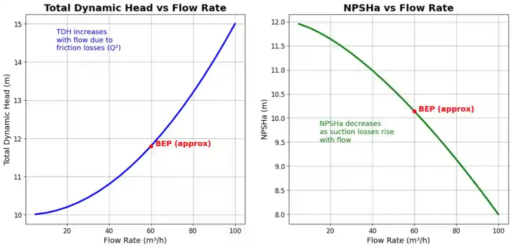
It calculates key values such as Total Dynamic Head (TDH), Net Positive Suction Head Available (NPSHa), friction losses, hydraulic power, and brake power. The calculator also provides a visual chart showing how these values change with flow rate, which helps in better pump selection and performance analysis.
Note: Use our Head Loss Calculator and Vapour Pressure Calculator for the tems used in the calculation here.
Related: NPSH (Net Positive Suction Head) Calculation for Pumps
Related: Head Loss or Pressure Loss Calculator using Darcy-Weisbach Equation
Related: Friction Factor Calculator Moody’s Diagram for Smooth and Rough Pipes
Centrifugal Pump Sizing Calculations
Centrifugal pump sizing calculations involve selecting the appropriate pump to meet the required flow rate and total head for a system. Choosing the correct pump is critical to ensure efficient operation, conserve energy, and prevent issues such as cavitation, noise, or premature wear.
Key factors to consider when selecting a pump include the desired flow rate, total dynamic head (accounting for elevation, friction, and pressure losses), fluid properties (such as density and viscosity), and available suction pressure (NPSH).
Here, we will discuss the terminology and formulas used for pump sizing calculations.
Below, we have included the video tutorial from ChemEnggCalc regarding Pump Sizing Explained: System Curve, NPSH & Cavitation (Centrifugal Pumps) to assist you in mastering the topic.
Total Dynamic Head (TDH)
Total Dynamic Head (TDH) is the total equivalent height that a fluid is to be pumped, including everything that adds resistance to the flow. It represents the total energy per unit weight of fluid that the pump must deliver.
Mathematically, Total Dynamic Head is given as:
TDH = Static Head (Hs) + Friction Losses (Hf) + Pressure Head (Hp) + Velocity Head (Hv)
where,
- 𝐻s is the Static Head represents the vertical height the fluid needs to be lifted from the source (like a tank or well) to the final discharge point.
- 𝐻f is the friction losses due to the resistance the fluid faces while moving through pipes, fittings, bends, valves, etc.
- 𝐻p is the Pressure Head is the extra pressure needed if it’s pushing into a pressurized system or tank to overcome it.
- 𝐻v = v2/2g is the Velocity Head, represents the energy needed to move the fluid at a certain speed through the discharge pipe.
The sum of these head components make up the Total Dynamic Head (TDH) — the total effort a pump needs to deliver the required flow.
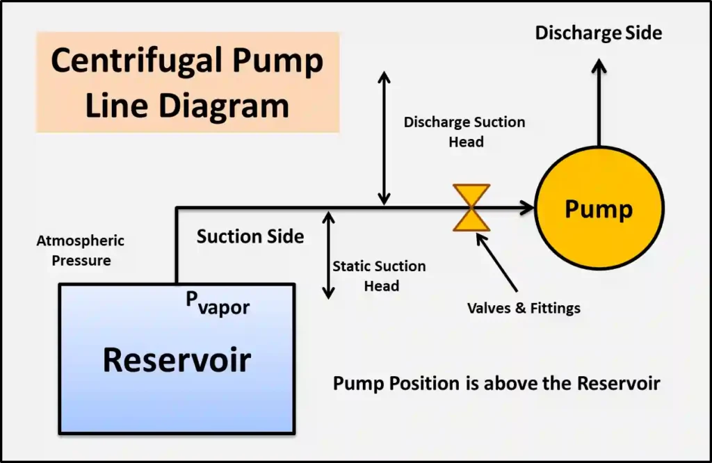
Note: Static Head in the calculation includes the suction static head (negative if the pump is above the source) and the discharge static head. Friction losses include the friction loss in the pipeline, valves, and fittings on both the suction and discharge sides, combined to give the overall friction loss.
To calculate head loss due to friction in the pipeline, we used the Darcy-Weisbach equation:
\[h_f = f \times \frac{L}{D} \times \frac{v^2}{2g}\]
For head loss due to fittings, we applied the formula:
\[h_f = K \times \frac{v^2}{2g}\]
where ( K ) is the fitting coefficient, such as for elbows.
Related: Newton’s Law of Viscosity Calculator – Dynamic Viscosity
Related: Hagen-Poiseuille Equation Calculator / Poiseuille’s Law Solver

Net Positive Suction Head (NPSH)
Net Positive Suction Head (NPSH) is a measure of absolute pressure at the suction inlet of a centrifugal pump, above the vapor pressure of the liquid being pumped, to prevent cavitation. It represents the difference between the pressure at the pump suction and the vapor pressure of the liquid being pumped, expressed as the head of a liquid.
Cavitation occurs when the liquid vaporizes due to low pressure, forming bubbles that collapse and cause damage to the pump. NPSH ensures the pump operates efficiently and reliably.
There are two types of NPSH:
- NPSH Available (NPSHa): The actual pressure head supplied by the system to the pump.
- NPSH Required (NPSHr): The minimum pressure head required by the pump to operate without cavitation, provided by the manufacturer.
Rule of Thumb: Always ensure NPSHa > NPSHr for safe operations without cavitation.
Formula for NPSH Available (NPSHa) is given as:
\[\text{NPSHa} = \frac{P_{\text{atm}} – P_{\text{vapor}}}{\rho g} + h_s – h_f\]
Or in simple terms:
NPSHa = Atmospheric Pressure Head − Vapor Pressure Head + Static Suction Head − Friction Losses in suction line
Related: Read our full article NPSH (Net Positive Suction Head) Calculation and Cavitation for Pumps
Hydraulic Power & Brake Power
Hydraulic power is the effective power delivered by a pump to move fluid against resistance, such as elevation, friction, or pressure. It represents the energy transferred to the fluid in the form of flow and pressure (head).
Hydraulic power depends on the flow rate, the total head, and the fluid’s density. It formula is given as:
\[P_h = \frac{\rho \cdot g \cdot Q \cdot H}{1000}\]
Where in S.I. units:
- H is the Total Dynamic Head (m)
- Ph is the Hydraulic Power (in kW)
- ρ is the fluid density (kg/m³)
- g is the acceleration due to gravity (m/s²)
- Q is the flow rate (m³/s)
Note: A higher flow rate required to pump the fluid means the pump must exert more pressure to lift the fluid, resulting in greater hydraulic power.
When a pump operates, energy is lost due to friction in pipes and fittings, leakage from backflow or internal clearances, mechanical losses, and heat from inefficiencies during fluid transport. Therefore, the pump’s efficiency is calculated to account for these losses.
Brake power is the actual mechanical power supplied to the pump shaft by the motor or engine. It is always greater than hydraulic power as it includes for all losses.
Brake Power = Hydraulic Power / η
The term η represents efficiency, expressed as a decimal (e.g., 0.70 for 70% efficiency). Brake power is typically measured in horsepower (hp) or brake horsepower (BHP).
Must Read: Personal Carbon Footprint Calculator – Track your CO2 Emissions
Also Read: Area of Cross-Section Calculator for Hollow Sections, Beams & Shapes

Resources
- “Fluid Mechanics” by Frank M. White
- “Introduction to Fluid Mechanics” by Robert W. Fox, Alan T. McDonald, and Philip J. Pritchard
- “Principles of Heat and Mass Transfer” by Frank P. Incropera and David P. DeWitt
- Python.org – The official Python website offers tutorials, documentation, and resources for learning Python.
Disclaimer: The Solver provided here is for educational purposes. While efforts ensure accuracy, results may not always reflect real-world scenarios. Verify results with other sources and consult professionals for critical applications. Contact us for any suggestions or corrections.