Table of Contents
Agitated vessels play an important role in industrial processes where mixing, heat transfer, or mass transfer is required. The power consumption in an agitated vessel helps in selecting the right motor size, optimizing energy use, and preventing equipment underperformance or overloading.
Power Consumption for an Agitated Vessel
Power consumption in an agitated vessel is the energy required to drive the impeller, which converts into the energy imparted to the fluid and leads to mixing or other desired effects.
The power requirement is the important factor in designing and operations of agitated vessels, as it directly impacts energy costs and process efficiency.
Impeller Agitator are of mainly two types:
- The one generate currents parallel with the axis of the impeller shafts know as Axial Flow Impellers
- Those generate currents in the tangential or radial direction know as Radial Flow Impellers
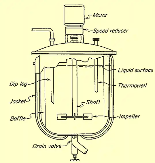
The power requirement for an agitated vessel is given by:
\[P = N_p \cdot \rho \cdot N^3 \cdot D^5\]
Where:
- D is the Impeller diameter (m)
- P is the power requirement (W or kW)
- Np is the Power number (dimensionless)
- \(\rho \) is the fluid density (kg/m3)
- N is the rotational speed (rps)
Related: Sphericity Calculator for different shapes
Related: Ergun Equation Calculator for Pressure Drop in Packed Bed Column
Power Consumption Calculator for an Agitator
The Power Requirement for an Agitator Calculator is a web tool designed to compute the power consumption to operate an agitator for a mixing application. User inputs the fluid density, viscosity, impeller speed, impeller diameter, power number, and viscosity factor.
Based on the given parameters, the calculator computes the Impeller Reynolds Number with its flow regime, the actual power required to drive the agitator (in kW), and the recommended motor size considering an efficiency of 85%.
Note: Follow the guide given below and put the values of Power Number based on impeller types, User may look for the literature and reference material provided in the resources here.
Related: Head Loss or Pressure Loss Calculator using Darcy-Weisbach Equation
Guide to Calculate the Power Requirement
The power requirement of an agitated vessel depends on various factors such as fluid properties, height of the liquid, tank dimensions, agitator type and speed of agitator.
Step 1. Determine the power number for impeller geometry.
The Power Number (Np) is a dimensionless parameter used to describe the power consumption of an impeller in a mixing process. Power number (Np) is a function of Reynolds number as well as impeller geometry.
Mathematically power number can be written as:
\[N_p = \frac{P}{\rho \cdot N^3 \cdot D^5}\]
Edition: 7th Edition, By: Warren L. McCabe, Julian C. Smith, Peter Harriott
A comprehensive resource on chemical engineering principles, covering core unit operations and practical applications essential for professionals and students alike.
Buy on AmazonIn the context of agitation and mixing in a vessel, the Reynolds Number (NRe) is a dimensionless quantity that characterizes the flow regime of the fluid being mixed. It is defined as:
\[N_{Re} = \frac{\rho \cdot N \cdot D^2}{\mu}\]
where in S.I units:
- NRe is the Impeller Reynolds number (dimensionless)
- \(\rho\) is Fluid density (kg/m3)
- N is the Impeller speed (rev/s)
- D is the Impeller diameter (m)
- \(\mu\) is the fluid viscosity (Pa·s)
The Reynolds number helps determine whether the flow is laminar, turbulent, or transitional:
- For Laminar flow (Re<10): Np is inversely proportional to Re. You may need chart or equation specific to the impeller type.
- For Turbulent flow (Re>10,000): Np is nearly constant for a given impeller. Use the standard Np values for the impeller type (e.g., 5.5 for flat-blade turbines).
- For Transitional flow (10≤Re≤10,000): Np gradually transitions between laminar and turbulent values.
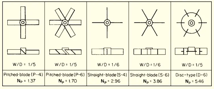
Image Source: Handbook of Chemical Engineering
The power number for the turbulent region is tabulated above. User first choose the type of agitator and then correction for standard power number as per the actual size of the agitator in the tank.
If (W/D)standard = 1/5 on table above :
Np = Npstandard * [(W/D)/(1/5)]1.25
If (W/D)standard = 1/6 on table above :
Np = Npstandard * [(W/D)/(1/6)]
where:
- Np is the power number in the geometry considered (-)
- Npstandard is the standard power number (-)
- W is the width of the blades of the impeller (m)
- D is the diameter of the impeller (m)
Step 2. Determine the power number at process conditions.
A correction factor based on NRe (impeller reynolds number) accounts primarily for the effects of viscosity on power. The Reynolds number is computed based on the formula given above.
The chart for Viscosity power factor as a function of impeller Reynolds number is given below:
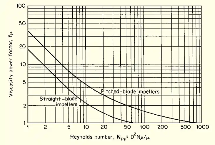
Therefore, the actual power number, Np(actual) is calculated by multiplying the viscosity power factor, fμ with the calculated power number, Np i.e Np(actual) = fμ * Np
Step 3. Determine the Motor Power to run the impeller
Now, we have calculated the actual power number at the process conditions. Therefore, from the basic definition of Power number the Power requirement can be calculated, using formula:
P = Npactual*(ρ . N3. D5)
Step 4. Select the Suitable Motor Size
An agitator contains a motor, gear reducer, shaft, and impeller(s). Gear reducer losses are minimal (3–8%), but deviations in speed and process conditions (density, viscosity) limit motor load to 85% of calculated impeller power.
Pmotor = Pactual / 0.85
Therefore, it is always advisable to choose the motor size of not more than 85% of its rated capacity to ensure reliable operation and avoid overloading.
Related: Bernoulli’s Equation Calculator / Solver – Interactive Python Code
Example Problem on Power Requirement for an Agitator
For a pitched-blade turbine impeller that is 58 in (1.47 m) in diameter and has four 12-in-wide (0.305-m) blades mounted at a 45◦ angle, determine the power required to operate the impeller at 84 r/min (1.4 r/s) in a liquid with a specific gravity of 1.15 (1150 kg/m3) and a viscosity of 12,000 cP (12 Pa · s). What size standard electric motor should be used to drive an agitator using this impeller?
Given Data:
- Impeller diameter, D = 1.47 m
- Impeller speed, (N) = 84 rpm = 1.4 rps
- Blade width (W) = 0.305 m
- Density (ρ) = 1150 Kg/m3
- Viscosity (μ) = 12 Pa.sec
We will be following the same step as given in this article, let’s calculate the reynolds number with the given values, we get:
The formula for Reynolds number is:
\[Re = \frac{\rho N D^2}{\mu}\]
Putting the values, we get:
\[Re = \frac{1150 \cdot 1.4 \cdot (1.47)^2}{12}\]
\[Re = 289.92\]
Since (Re < 10,000), there the flow regime is Transition.
Now, based on the flow regime we will be calculating the power number Np from the chart given above for Pitched Blade Impeller.
The blade width-to-diameter ratio W/D is not exactly 1/5. To correct for the effect of a nonstandard W/D on a four-blade impeller, a factor of actual W/D to standard W/D raised to the 1.25 power must be applied to the standard turbulent power number NP = 1.37.
Np = Npstandard * [(W/D)/(1/5)]1.25
Np = 1.37 * [0.305/1.47)/(1/5)]1.25
Power Number, Np= 1.43
Therefore, the power number for the given geometry is 1.43
Power Number Correction for the given process condition using the chart Reynolds Number vs viscosity correction factor (fμ = 1.2)
Np(actual) = fμ * Np
Np(actual) = 1.2 * 1.43 = 1.72
The formula for power is:
P = Npactual*(ρ . N3. D5)
P = 1.72 * 1150 * 1.43 * 1.475 /1000
Actual power, P = 37.7 kW
To account for motor efficiency, taking \(\eta = 85\%\):
\[\text{Motor Size} = \frac{\text{Actual Power}}{\eta}\]
Substitute the values:
\[\text{Motor Size} = \frac{37.7}{0.85} = 44.3 \, \text{kW}\]
Hence, Select a standard motor of available size more than the given motor size i.e 45 kW
Related: Reynolds Number Calculator for a Circular Pipe
Related: Kick’s Law Calculator
Edition: 9th Edition, By: Don W. Green, Marylee Z. Southard
The ultimate resource for chemical engineering, covering core concepts, data, and insights. An invaluable reference for students, engineers, and industry professionals.
Buy on AmazonResources:
- “Unit Operations in Chemical Engineering” (McCabe et al.)
- “Particle Technology and Separation Processes” (Richardson et al.)
- “Chemical Engineering Design: Principles, Practice and Economics of Plant and Process Design” (Towler and Sinnott)
- Handbook of Chemical Engineering calculations, Chopey et al, McGraw Hill, 2004
Disclaimer: The Solver provided here is for educational purposes. While efforts ensure accuracy, results may not always reflect real-world scenarios. Verify results with other sources and consult professionals for critical applications. Contact us for any suggestions or corrections.

