Table of Contents
As fluid flows through pipes, friction from surface roughness and flow velocity causes pressure and head losses. These losses result from pipe friction and fittings such as elbows, which impact system efficiency.
Our ChemEnggCalc’s Pipe and Fittings Pressure Loss Calculator helps engineers and students design HVAC, water, and industrial piping systems by accurately computing losses using the Darcy-Weisbach equation and K or L/D methods.
Related: Head Loss or Pressure Loss Calculator using Darcy-Weisbach Equation
Pipe and Fittings Pressure Loss Calculator
This ChemEnggCalc’s Pipe and Fittings Pressure Loss Calculator in Piping System accurately computes pressure and head losses for pipes and fittings using the Darcy-Weisbach equation and K or L/D methods.
This calculator supports multiple units and fluid presets, allows custom value inputs, and delivers accurate Total System Pressure Loss results for both pipe friction and fittings in piping systems.
Related: NPSH (Net Positive Suction Head) Calculation for Pumps
Related: Friction Factor Calculator Moody’s Diagram for Smooth and Rough Pipes
Pipe and Fittings Losses in Piping System
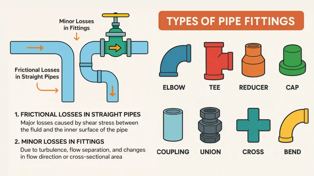
Losses in a Piping System refer to the pressure drops or energy losses experienced by a fluid as it flows through straight pipes and fittings (such as elbows, tees, valves, and reducers) due to friction and flow disturbances.
These losses primarily arise from two sources:
- Frictional Losses in Straight Pipes – These are major losses caused by shear stress between the fluid and the inner surface of the pipe.
- Minor Losses in Fittings – These occur due to turbulence, flow separation, and changes in flow direction or cross-sectional area.
Frictional losses depend on factors such as pipe length, diameter, surface roughness, fluid velocity, and viscosity. They are typically calculated using the Darcy-Weisbach equation.
The Darcy-Weisbach equation for pressure drop (ΔP) due to friction in a pipe is given by:
\[\Delta P = f \cdot \left( \frac{L}{D} \right) \cdot \left( \frac{\rho v^2}{2} \right)\]
where:
- ΔP is the Pressure drop (Pa or N/m²)
- hf is the head loss (m)
- f is the Darcy friction factor (dimensionless)
- L is the Length of the pipe (m)
- D is the Diameter of the pipe (m)
- \(\rho\) is the Fluid density (kg/m³)
- \(v\) is Velocity of the fluid (m/s)
Minor losses are quantified using loss coefficients (K) or equivalent lengths (L/d) for various fittings and components. Below is the table provided for the K and L/d values for different types of fittings in the pipeline and used in the calculator above.
| Fitting | Loss Coefficient (K) | Equivalent Length (L/d) |
|---|---|---|
| 90° Elbow (Standard) | 0.75 | 35 |
| 90° Elbow (Long-Radius) | 0.5 | 22.5 |
| 45° Elbow | 0.35 | 17.5 |
| Tee (Run) | 0.15 | 15 |
| Tee (Branch) | 0.85 | 55 |
| Gate Valve (Fully Open) | 0.15 | 8 |
| Globe Valve (Fully Open) | 7.0 | 340 |
| Ball Valve (Fully Open) | 0.075 | 4 |
| Check Valve | 1.5 | 100 |
| Reducer (Concentric) | 0.3 | 15 |
| Expander (Concentric) | 0.75 | 25 |
These losses result in a reduction in fluid pressure and energy, which necessitates higher pump or compressor power to maintain the desired flow rate. This, in turn, increases operational costs and can impact system efficiency.
Therefore, careful design is essential to minimize these losses through appropriate pipe sizing, material selection, and fitting optimization.
To calculate pressure loss and head loss due to fittings in a pipeline, engineers commonly use the K-factor method, which is based on the loss coefficient K of each fitting.
The formula for Pressure Loss for K-factor method is given as:
\[\Delta P = K \cdot \frac{1}{2} \rho\]
- ΔP is the Pressure loss due to fitting (Pa)
- K is the Loss coefficient (dimensionless, specific to the type of fitting)
- ρ is the Fluid density (kg/m³)
- v is the Fluid velocity (m/s)
The formula for Head Loss (hL) for K-factor method is given as:
\[h_L = K \cdot \frac{v^2}{2g}\]
- hL is the Head loss due to fitting (m)
- g is the Acceleration due to gravity (9.81 m/s²)

Another method expresses the loss caused by a fitting as an equivalent length of straight pipe (Leq), which causes the same frictional loss.
The formula of Pressure Loss ( ΔP) for equivalent length method is given as:
\[\Delta P = f \cdot \frac{L_{eq}}{D} \cdot \frac{1}{2} \rho v^2\]
- ρ is the Fluid density (kg/m³)
- ΔP is the Pressure loss (Pa)
The formula of Head Loss (hL) for equivalent length method is given as:
\[h_L = f \cdot \frac{L_{eq}}{D} \cdot \frac{v^2}{2g}\]
- hL is the Head loss (m)
- f is the Darcy friction factor (dimensionless)
- Leq is the Equivalent length of pipe for the fitting (m)
- D is the Pipe inner diameter (m)
- v is the Fluid velocity (m/s)
- g is the Acceleration due to gravity (9.81 m/s²)
Related: Newton’s Law of Viscosity Calculator – Dynamic Viscosity
Related: Hagen-Poiseuille Equation Calculator / Poiseuille’s Law Solver
Resources
- “Fluid Mechanics” by Frank M. White
- “Introduction to Fluid Mechanics” by Robert W. Fox, Alan T. McDonald, and Philip J. Pritchard
- “Principles of Heat and Mass Transfer” by Frank P. Incropera and David P. DeWitt
- Python.org – The official Python website offers tutorials, documentation, and resources for learning Python.
Disclaimer: The Solver provided here is for educational purposes. While efforts ensure accuracy, results may not always reflect real-world scenarios. Verify results with other sources and consult professionals for critical applications. Contact us for any suggestions or corrections.