Table of Contents
In Reaction Engineering, multiple reactor system like combination of Plug Flow Reactor (PFR) and Continuous Flow Stirred Reactor, CSTR in series or parallel arrangement provides better control, flexibility, and efficiency in chemical processes. These configurations are widely used in various industries from pharmaceuticals to petrochemicals, ensuring optimal performance, product quality and economics.
Plug Flow Reactors in Series
For Plug Flow Reactors (PFRs) in series, the reactors are arranged in sequential manner that the outlet of one reactor becomes the inlet of the next. The reaction progresses through each reactor, with the overall conversion increasing across the series.
Related: Plug Flow Reactor – Design Equation and Calculations
Consider N plug flow reactors connected in series, and let X1, X2 , . . . , XN, be the fractional conversion of component A leaving reactor 1, 2, . . . , N having volume of reactor V1, V2 . . . . VN respectively.

The general design equation for a single Plug Flow Reactor (PFR) is:
\[\frac{dF_A}{dV} = -r_A\]
In terms of conversion X, the design equation becomes:
\[V = \int_{X_0}^{X} \frac{F_{A0}}{-r_A} dX\]
where:
- \(X_0\) is the initial conversion (at the inlet),
- \( X \) is the final conversion (at the outlet),
- \( F_{A0} \) is the molar flow rate of A at the inlet,
- \( r_A \) is the rate of reaction, which depends on the concentration of ( A ).
For Reactor 1, with an inlet molar flow rate \( F_{A0} \) and an initial conversion \( X_0 = 0 \):
\[V_1 = \int_{X_0}^{X_1} \frac{F_{A0}}{-r_A} dX\]
where X1 is the conversion after Reactor 1 and V1 is the volume of Reactor 1.
The concentration of ( A ) at any point in Reactor 1 is related to the conversion by:
For Reactor 2, the inlet molar flow rate is \( F_{A1} \) (the flow rate exiting Reactor 1), and the conversion at the inlet is X1. The design equation for Reactor 2 is:
\[V_2 = \int_{X_1}^{X_2} \frac{F_{A0}}{-r_A} dX\]
where X2 is the conversion after Reactor 2 and V2 is the volume of Reactor 2.
Therefore, the generalized Equation for N PFR in Series, the conversion increases from X0 at the inlet of the first reactor to XN at the outlet of the Nth reactor. The design equation for the ith reactor is:
\[V_i = \int_{X_{i-1}}^{X_i} \frac{F_{A0}}{-r_A} dX\]
where:
- \( X_{i-1} \) is the conversion at the inlet of reactor ( i ),
- \( X_i \) is the conversion at the outlet of reactor ( i ),
- \( V_i \) is the volume of reactor ( i ).
The total volume required for the series of reactors is:
\[V_{\text{total}} = V_1 + V_2 + \dots + V_N\]
or, we can say that,
\[V_{\text{total}} = \int_{X_0}^{X_N} \frac{F_{A0}}{-r_A} dX\]
Hence, N plug flow reactors in series with a total volume V gives the same conversion as a single plug flow reactor of volume V. we can treat the whole system as a single plug flow reactor of volume equal to the total volume of the individual units.
PFR in series can be useful for enhancing conversion by increasing the total residence time of reactants. It can also be used to maintain steady-state conditions if reactions occur in stages or require different conditions.
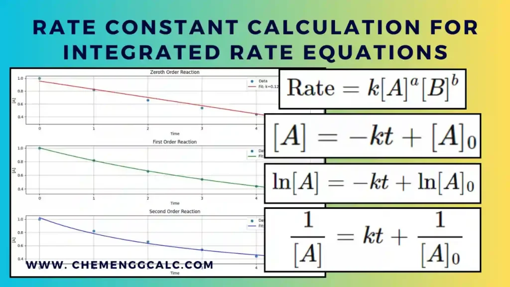
Related: Rate Constant Calculation for Zeroth, First and Second Order using Integrated Rate Equations
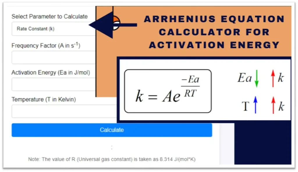
Related: Arrhenius Equation Calculator for Activation Energy
CSTR in Series
In Continuous Stirred Tank Reactors (CSTRs) connected in series, the outlet of the first reactor becomes the inlet of the second reactor, and so on. CSTR operates at a steady state with complete mixing, the concentration of the reactants is uniform throughout the reactor.
Related: Mixed Flow Reactor – Design Equation and Calculations
The reactant that enters the first reactor undergoes partial conversion, then fed into second reactor for further conversion and this process continues across all reactors. The total conversion for the system is the cumulative effect of each reactor connected in series.
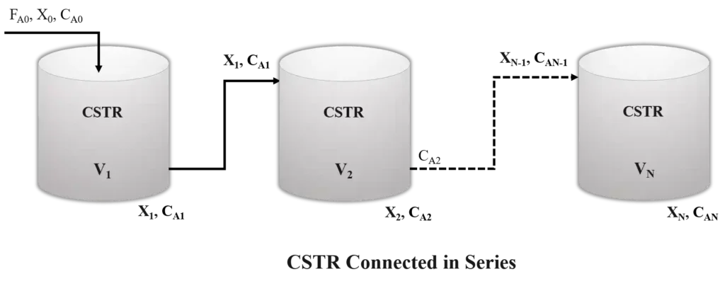
Consider N CSTRs connected in series, and let X1, X2 , . . . , XN, be the fractional conversion of component A leaving reactor 1, 2, . . . , N having volume of reactor V1, V2 . . . . VN respectively assuming the first order reaction within the reactor.
The general design equation using material balance for a single CSTR is given by:
\[C_{A0} – C_A = -r_A \tau\]
Where:
- CA0 is the initial concentration of reactant ( A ) entering the reactor.
- CA is the concentration of ( A ) leaving the reactor.
- rA is the reaction rate (mol/m³·s).
- \( \tau \) is the residence time defined as \( \tau = \frac{V}{F_{A0}} \).
Design equation for the first reactor, the inlet concentration is CA0 and the outlet concentration is CA1 given as:
\[C_{A0} – C_{A1} = -r_{A1} \tau_1\]
For a first-order reaction, we get,
\[C_{A0} – C_{A1} = -k C_{A1} \tau_1\]
Rearranging this equation gives:
\[C_{A1} = \frac{C_{A0}}{1 + k \tau_1}\]
similarly, for the second reactor, the inlet concentration is CA1 and the outlet concentration is CA2 the design equation becomes:
\[C_{A2} = \frac{C_{A1}}{1 + k \tau_2}\]
substituting CA1 from Reactor 1 gives:
\[C_{A2} = \frac{C_{A0}}{(1 + k \tau_1)(1 + k \tau_2)}\]
Therefore, the generalized equation for N CSTRs in Series, the design equation for the ith reactor for the first order reaction for a subsequent reactor is given by:
\[C_{A_i} = \frac{C_{A_{i-1}}}{1 + k \tau_i}\]
In terms of conversion Xi in the ith reactor is defined as:
\[X_i = \frac{C_{A0} – C_{A_i}}{C_{A0}}\]
Now, substituting recursively, the concentration after the Nth reactor becomes:
\[C_{A_N} = \frac{C_{A0}}{(1 + k \tau_1)(1 + k \tau_2) \cdots (1 + k \tau_N)}\]
In terms of conversion after N reactors, the overall conversion is:
\[X_N = \frac{C_{A0} – C_{A_N}}{C_{A0}} = 1 – \frac{C_{A_N}}{C_{A0}}\]
substituting the value of \(C_{A_N}\) we get:
\[X_N = 1 – \frac{1}{(1 + k \tau_1)(1 + k \tau_2) \cdots (1 + k \tau_N)}\]
Above equation provide the generalized form of N CSTR connected in series for first order reaction.
For equal volumes of reactors i.e each reactor has the same volume V and residence time \(\tau\).
\[\tau_1 = \tau_2 = \dots =\tau_N\]
Putting the value of \(\tau\) in generalized form of CSTR in series, we get:
\[C_{A_N} = \frac{C_{A0}}{(1 + k \tau)^N}\]
The overall conversion after N reactors is given by:
\[X_N = 1 – \frac{C_{A_N}}{C_{A0}} = 1 – \frac{1}{(1 + k \tau)^N}\]
As N increases (\(N \to \infty\)) the behavior of CSTRs in series approaches that of a PFR. The series becomes a continuous process and the resulting conversion becomes equivalent that of a PFR due to reduced back-mixing.
For a PFR the overall conversion is given as \(X = 1 – e^{-k \tau}\)
As N increases and \( \tau \) remains constant, equation \(X_N = 1 – \frac{1}{(1 + k \tau)^N}\) to \(X_N = 1 – e^{-k \tau}\) as \(N \to \infty\).
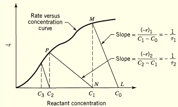
Image Source: Levenspiel, Arthur W. Chemical Reaction Engineering. 3rd ed., Wiley, 1999
CSTR in series, becomes the good option in industrial scale as it provides improved overall conversion of reactants to products compared to a single CSTR. It has also the ability to operate reactors under different conditions to optimize complex reactions.
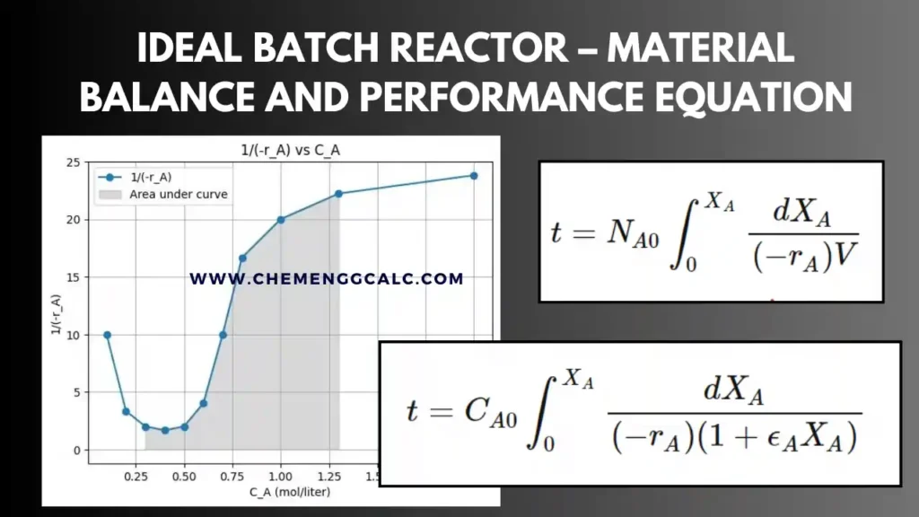
Related: Ideal Batch Reactor – Material Balance and Performance equation Calculations
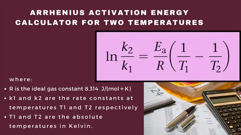
Related: Arrhenius Activation Energy Calculator for two temperatures
Plug Flow Reactor in Parallel
In a parallel configuration of plug flow reactors (PFRs), multiple reactors can be operated simultaneously (concurrent), with the same feed stream entering each reactor and then mixing before exiting the system.
Consider two PFRs are connected in parallel with the inlet flow rate of reactant A is FA0 which splits into two molar flow rates of FA1 and FA2 with volumes of reactor V1 and V2 having conversion in each reactor of X1 and X2 respectively.
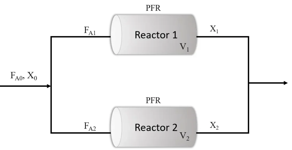
The total inlet flow rate FA0 is given as FA0 = FA1 + FA2
For reactor 1 and reactor 2 the design equation for each reactor are given as:
\[V_1 = \int_{X_0}^{X_1} \frac{F_{A1}}{-r_A} dX\]
\[V_2 = \int_{X_0}^{X_2} \frac{F_{A2}}{-r_A} dX\]
The total volume for the two reactors in parallel is:
\[V_{\text{total}} = V_1 + V_2\]
The overall conversion \( X_{\text{total}} \) for the parallel configuration can be calculated from the outlet flow rates:
\[F_{A,\text{total}} = F_{A1}(1 – X_1) + F_{A2}(1 – X_2)\]
The overall conversion is given by:
\[X_{\text{total}} = \frac{F_{A0} – F_{A,\text{total}}}{F_{A0}}\]
Therefore, the generalized form for N reactors in Parallel, the total outlet flow rate and overall conversion can be given as:
\[F_{A,\text{total}} = \sum_{i=1}^{N} F_{Ai}(1 – X_i)\]
\[X_{\text{total}} = \frac{F_{A0} – F_{A,\text{total}}}{F_{A0}}\]
Parallel reactors allow for varying residence times and conditions. If all reactors are identical, they might yield a higher overall conversion due to their independent operation.
For the optimum results of plug flow reactors connected in parallel or in any parallel-series combination, we can treat the whole system as a single plug flow reactor of volume equal to the total volume of the individual units if the feed is distributed in such a manner that fluid streams that meet have the same composition
Related: Plug Flow Reactor – Design Equation and Calculations
CSTR in Parallel
In CSTR connected in parallel means multiple reactors operate simultaneously, receiving the same feed stream. This setup allows for higher overall throughput and different reaction conditions.
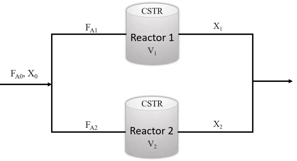
Consider two CSTRs are connected in parallel with the inlet flow rate of reactant A is FA0 which splits into two molar flow rates of FA1 and FA2 with volumes of reactor V1 and V2 having conversion in each reactor of X1 and X2 respectively.
For Reactor 1 the design equation for first order reaction assuming FA1=FA2=FA0/2 which means equal feed split between the reactors and having same volume V1 = V2 = V
\[\frac{F_{A0}}{2} (C_{A0} – C_{A1}) = k C_{A1} V\]
Similarly for reactor 2
\[\frac{F_{A0}}{2} (C_{A0} – C_{A2}) = k C_{A2} V\]
we found the conversions remain same therefore for two CSTR in parallel configuration the outlet concentration are given as:
\[C_{A1} = C_{A2} = \frac{C_{A0}}{1 + \frac{2kV}{F_{A0}}}\]
The total conversion for N CSTR in parallel, the outlet concentration is given by:
\[C_{A_{out}} = \frac{C_{A0}}{1 + \frac{NkV}{F_{A0}}}\]
CSTRs in parallel is useful in the processes where flexibility of managing reaction conditions is required and this can help in achieving better throughput. The total conversion is governed by the characteristics of individual reactors combined with the overall flow and concentration dynamics.
Related: Mixed Flow Reactor – Design Equation and Calculations
Python Code for CSTR in Series Vs Single PFR
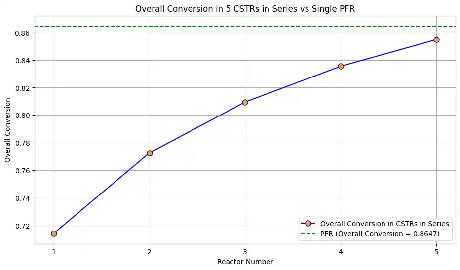
This Python code helps user to calculate and visualize the cumulative conversion of reactant A when CSTR reactor is connected in series arrangement and then compares it with the overall conversion in a single Plug Flow Reactor (PFR) of the same total volume.
User can modify the values of k, V_total, Q, and num_cstrs to see different scenarios and on executing the script observe the printed outputs and graph for better understanding.
Note: This Python code solves the specified problem for 1st order reaction. Users can copy the code and run it in a suitable Python environment. By adjusting the input parameters, and observe how the output changes accordingly.
import numpy as np
import matplotlib.pyplot as plt

# Parameters
k = 1     # Reaction rate constant (1/min)
V_total = 10.0  # Total volume of the reactors (L)
Q = 5.0        # Volumetric flow rate (L/min)
C_in = 10.0    # Initial concentration of A (mol/L)

# Number of CSTRs in series
num_cstrs = 5
V_cstr = V_total / num_cstrs  # Volume of each CSTR

# CSTR Calculations for Cumulative Conversion
X_cstr_cumulative = np.zeros(num_cstrs + 1)  # Cumulative conversion after each CSTR
X_cstr_cumulative[0] = 0  # Initial cumulative conversion (no reaction has occurred)

for i in range(1, num_cstrs + 1):
    # Conversion in the current CSTR step
    X_i = (1 - X_cstr_cumulative[i-1]) / (1 + k * V_cstr / Q)
    # Update cumulative conversion
    X_cstr_cumulative[i] = X_cstr_cumulative[i-1] + X_i * (1 - X_cstr_cumulative[i-1])

# PFR Calculation for Overall Conversion
X_pfr = 1 - np.exp(-k * V_total / Q)

# Display conversions
print(f"Cumulative conversions after each CSTR:")
for i in range(1, num_cstrs + 1):
    print(f"After CSTR {i}: {X_cstr_cumulative[i]:.4f}")

print(f"\nOverall conversion in PFR: {X_pfr:.4f}")

# Plotting
plt.figure(figsize=(11, 6))
cstr_indices = np.arange(1, num_cstrs + 1)

# Plot cumulative conversion for CSTRs in series
plt.plot(cstr_indices, X_cstr_cumulative[1:], 'o-', label='Overall Conversion in CSTRs in Series', color='blue', markerfacecolor='orange', markersize=8)

# Plot single PFR conversion
plt.axhline(y=X_pfr, color='green', linestyle='--', label=f'PFR (Overall Conversion = {X_pfr:.4f})')

# Plot formatting
plt.xlabel('Reactor Number')
plt.ylabel('Overall Conversion')
plt.title(f'Overall Conversion in {num_cstrs} CSTRs in Series vs Single PFR')
plt.xticks(cstr_indices)
plt.grid(True)
plt.legend()
plt.show()
Output:
Cumulative conversions after each CSTR:
After CSTR 1: 0.7143
After CSTR 2: 0.7726
After CSTR 3: 0.8095
After CSTR 4: 0.8354
After CSTR 5: 0.8548

Overall conversion in PFR: 0.8647
Resources:
- Chemical Reactor Analysis and Design Fundamentals by Rawlings and Ekerdt
- Elements of Chemical Reaction Engineering by Fogler
- “Chemical Reaction Engineering“ by Octave Levenspiel
Disclaimer: The content provided here is for educational purposes. While efforts ensure accuracy, results may not always reflect real-world scenarios. Verify results with other sources and consult professionals for critical applications. Contact us for any suggestions or corrections.


